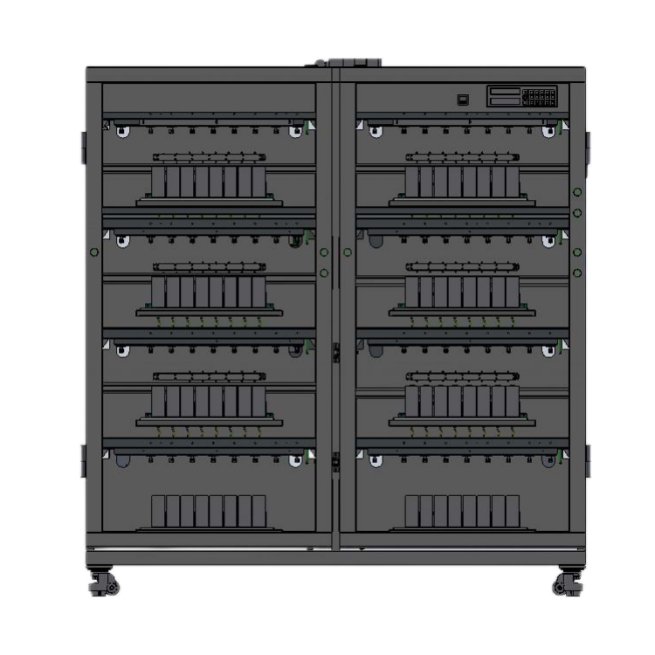
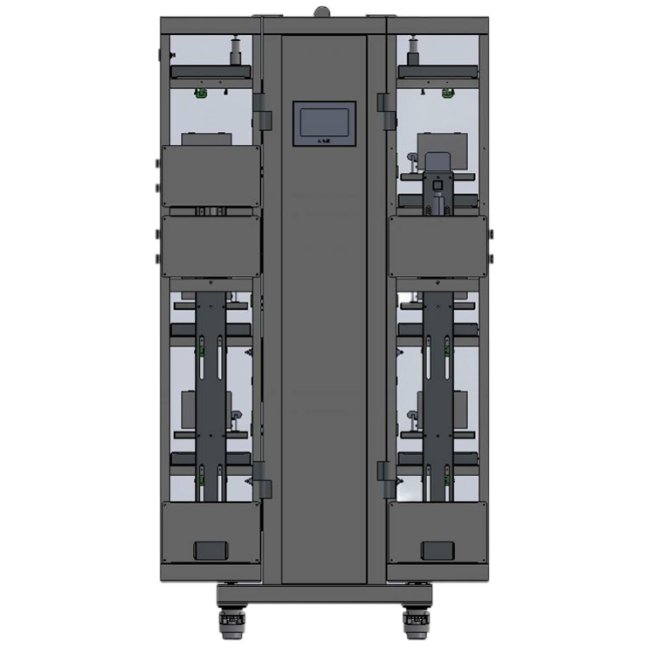
XW-5V40A128CH37 Prismatic Battery Cell Vacuum Negative Pressure Forming Machine
- Home
- Prismatic battery pack machine
- Prismatic cell grading machine
- XW-5V40A128CH37 Prismatic Battery Cell Vacuum Negative Pressure Forming Machine
Model: XW-5V40A128CH
Max votage: 5V
Max current: 40A
Channels: 128
Vacuum grade: -100KPa~0
Cell: Prismatic type
Usage: for prismatic cell forming with negative pressure
Type: Energy regenerative
Certification: CE
MOQ: 1 pcs
Leading time: 10-15 days
Warranty: 1 year
- Description
- Parameters
1. Equipment Introduction
1.1 Introduction to equipment structure and working principle
1.1.1 Equipment Overview
| Serial number | Device Name | Acceptance product model specifications |
| 1 | Prismatic Battery Cell Vacuum Forming Machine | XW-5V30A128CH37 |
This equipment is mainly used to test the voltage, capacity and other parameters of the negative pressure formation/ capacity division of square aluminum shell batteries, and completes the negative pressure formation process of the battery through a negative pressure vacuum system. It has a negative pressure reflux function and can classify the battery and perform data analysis and upload and share it according to the test results. It adopts an open-frame self-clamping tray electric clamping mode, a double-sided four-door structure, each door is divided into four layers, each layer has 8 battery stations, a total of 128 stations.
1.1.2 Equipment Features
- The equipment is divided into two parts, the power supply host part and the open frame self-clamping tray structure part.
- The circuit part is mainly composed of a mid-position machine board, a 30A constant current and constant voltage module, a bidirectional inverter switching power supply, a keyboard board, a PLC, a touch screen, etc.
- The power supply uses an intelligent bidirectional power supply with PFC filtering and built-in filtering.
- The circuit part adopts hardware bidirectional DC/DC design, which has high efficiency, fast response speed, comprehensive protection measures, low heat generation and more stable performance. The voltage and current calibration values of each motherboard are saved independently and can be replaced at will without adjusting the accuracy separately.
- It has data acquisition and TC/IP communication or 485 communication functions, and the minimum data recording interval can reach 1S.
- Supports automatic calibration function, which can automatically calibrate the accuracy through tooling and output it into a report.
- With database interface function, the capacity sharing data can be automatically uploaded to the data server.
- It has complete safety protection functions, including emergency stop, capacity protection, power failure continuity, offline operation and other functions.
- It has complete channel protection functions, including over-capacity protection, over-voltage, under-voltage protection, voltage and current fluctuation protection, battery reverse connection protection, over-current protection, trend protection, expected voltage and current protection functions.
- The electric clamping method is adopted, and the battery cell pole is in direct contact with the clamp.
- The contact surface is designed with teeth for better contact.
- The probe fixture/chip fixture line is fastened by screws and directly connected from the power module mainboard to the probe, reducing the risk of poor contact caused by line switching and improving efficiency. The line and the probe correspond one to one, which is convenient for maintenance and replacement.
- The battery probe module is responsible for reliably connecting the positive and negative poles of the battery during charging and discharging to form a test circuit.
- The device scans the code manually.
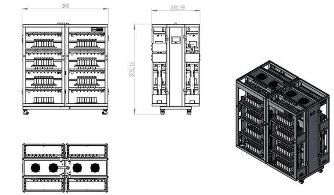
1.1.3 3D Appearance


Equipment engineering plan (size is for reference only, the actual size shall prevail)

Equipment size: length × width × height = 1950mm × 1093mm × 2032mm
1.1.4 Equipment workflow diagram
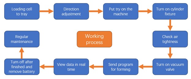
Negative pressure vacuum system working process description:
- First load the battery into the self-gripping tray, then adjust the battery filling port to the specified uniform direction and prepare for testing.
- After the battery is loaded into the equipment, turn on the drive cylinder switch, and the cylinder drives the probe clamp assembly and the vacuum suction cup assembly to clamp the battery up and down. At the same time, there is no gap and seamless connection between each battery filling port and the vacuum suction cup.
- After the battery probe fixture is clamped and the vacuum suction cup is connected to the battery injection port, open the vacuum regulating valve and set the vacuum valve to -90kps (or the process setting value can be adjusted to -100Kpa to 0Kpa during the negative pressure process), and check the vacuum degree in the vacuum gauge within the specified time (if the value in the vacuum gauge does not reach -90kps, please check whether there is leakage between the battery injection port and the vacuum suction cup or other connections). A pressure gauge is bypassed in the negative pressure unit pipeline to display its pressure value. It is installed in a convenient and visible area for easy observation.
- After checking that the air tightness is qualified, start the formation charging process and the negative pressure vacuum system.
- When the formation charging process is completed or the device has an abnormal alarm, first close the vacuum valve to release the vacuum state, and then unload the battery or handle the problem.
- After the formation and charging is completed, first close the vacuum regulating valve, then close the pneumatic switch of the fixture, and then remove the battery tray, and the formation is completed.
- During long-term operation of the equipment, it is necessary to frequently check whether the vacuum suction cup and vacuum pipeline have crystallization. If crystallization is found, please clean or replace the accessories in time to prevent air leakage.
- Vacuuming speed ≥50KPa/min; vacuum breaking speed ≥20KPa/s; leakage rate ≤1KPa/min (test after negative pressure extraction and pressure stabilization).
1.2 Main structure of the equipment
- Open-frame negative pressure formation equipment for lithium batteries.
- Computer with USB port (self-provided).
- USB to 485 interface converter and communication line or TCP communication.
- Battery scanning system.
- Product software.
2. Product specifications and fixture types compatible with the equipment
2.1 Device compatible product specifications
Self-clamping tray, suitable for battery size: battery length 65mm-220mm; width 20mm-70mm; height 90mm-230mm; pole ear center distance 45-160mm. Cylinder 80-20. (Note: This equipment is custom designed, one model of negative pressure formation equipment only supports one specification of battery)
2.2 Tray or fixture type
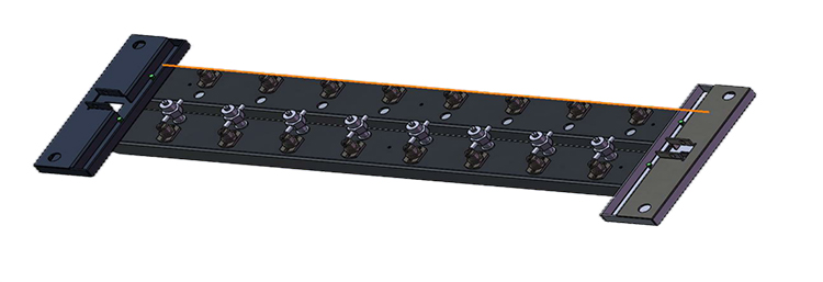
37-128-30A partial schematic diagram (Note: the above tooling can only fit the battery size provided by the purchaser)
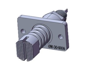
Customized fixture type
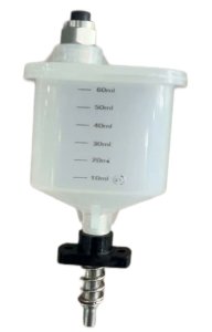
Negative pressure reflux cup (customized)
Equipment technical parameters
|
Equipment structure |
|
| Number of device channels | The whole machine has 128 channels |
| Chassis color | Standard gray/gray black (customizable) |
| Fixture form | Enhanced flat head clamp |
| Fixture spacing | Battery spacing 78.5MM |
| Channel control mode | Each battery has its own independent constant current and voltage source, which is stable and shock-free. It can realize start, stop, pause, continue and protection. |
| Each channel has independent constant voltage and constant current hardware control circuit | |
| The accuracy of each channel’s charging current and discharging current can be automatically calibrated by software | |
| Working power supply | Three-phase five-wire system AC380V±10%, 50HZ |
| Power Factor | 0.99 @220VAC, full load, grid THDu ≤2% |
| Current harmonics | <5% @220VAC, full load, grid THDu ≤2% |
| Power supply efficiency index | Charge ≥ 80%, discharge ≥ 70% |
| Working power consumption | ≤23KW |
| Grid voltage | 176 – 264V AC |
| Grid connection frequency | 47 – 53 Hz |
| Bidirectional drive mode | Synchronous Rectification |
| Discharge feedback to the grid | Same frequency and same amplitude |
| Feeding island protection function | have |
| Equipment failure rate | <1% |
| Work Environment | Temperature -10~40, relative humidity 80% |
| Status indicator | Status three-color light |
| Cooling method | Natural air intake, upward exhaust |
| Negative pressure range | (-100KPa-0) adjustable |
| Power component protection function | 1. Grid voltage over-limit protection
2. Grid frequency over-limit protection |
|
Channel parameters |
|
| Charging constant voltage mode | Hardware constant voltage, constant current and constant voltage conversion is smooth and impact-free |
| Voltage measurement range | DC 0~5V |
| Battery voltage range | Charging DC 0~4.5V; Discharging DC 4.5~2V |
| Constant voltage range | DC 2~4.5V |
| Voltage accuracy | ±(0.5 ‰ reading + 0.5 ‰ full scale), |
| Temperature coefficient | (±0.001%rdg.±0.3dgt.)/°C |
| Voltage control resolution | 0.1mV |
| Voltage sampling resolution | 0.1mV |
| Current range | Charging DC 100mA~40A; Discharging DC 100mA~40A |
| Current accuracy | ±(0.5 ‰ reading + 0.5 ‰ full scale) |
| Temperature coefficient | (±0.01%rdg.±0.3dgt.)/°C |
| Current control resolution | 1mA |
| Current sampling resolution | 1mA |
| Current rise time (90% load) | ≤50MS |
| Channel startup time (90% load) | ≤50MS |
|
Software Features |
|
| Control method | Computer controlled equipment operation, whole cabinet control/single point start, with scanning system |
| Communication | 485 serial port communication (baud rate 57600)/TCP communication |
| Process Settings | Up to 64 steps and 256 cycles can be set |
| Charging Mode | Constant current, constant voltage, constant current and constant voltage |
| Charging end condition | Voltage, current, time, capacity, -△V |
| Discharge mode | Constant current, constant power, constant resistance |
| Discharge end condition | Voltage, time, capacity |
| Protection function | 1. Charge overvoltage protection, charge undervoltage protection;
2. Discharge overvoltage protection, discharge undervoltage protection; 3. Charge and discharge voltage trend protection; 4. Voltage fluctuation protection; 5. Current fluctuation protection; 6. Battery reverse connection protection, hardware protection mode; 7. Power tube short circuit protection; 8. Channel capacity alarm protection (timeout protection); 9. Voltage sampling offline protection; 10. Voltage outlier protection; 11. Capacity outlier protection; 12. Voltage detection before the process starts, stop the channel with voltage exceeding the limit; 13. Power off protection, data breakpoint recovery. |
| Machine protection function | 1. The whole machine can set the global upper and lower limit protection voltage.
2. Power failure protection, data breakpoint recovery 3. Support offline mode: When the device is in offline operation state (that is, the device is disconnected from the host computer), the lower computer can save the data according to the configuration requirements, and can restore the uploaded test data after being online. The offline time can be up to 12 hours; if the time is exceeded, the “first in, first out” principle is adopted and the data is overwritten. 4. An emergency stop button is set on the equipment end. When the emergency stop occurs, the fixture will automatically release the connection between the battery and the fixture. |
| Time Range | 0~3000 minutes/step, time unit is min |
| Time accuracy | ≤±1‰ |
| Sampling inspection cycle | 1-60S optional |
| Battery sorting | Sorting by (capacity, time, open circuit voltage, discharge platform, etc.) |
| Data processing | It can record voltage, current, time, capacity data, automatically calculate constant current charging ratio, capacity loss, discharge efficiency, average voltage, median voltage and other data, and provide data curve graphs and cycle graphs; it can output to generate text, EXCEL, WODR or MDB database format file |
| Basic functions of the software | 1. The software supports various connection resumptions, such as manual pause resumption, software shutdown resumption, power failure interruption resumption, device communication interruption resumption, and abnormal stop resumption;
2. Support barcode scanning, can scan one-dimensional code and two-dimensional code, with sequential scanning, channel skip scanning, loading scanning and other scanning methods; 3. Detailed local test data storage allows you to view the current test data and historical data of each channel at any time. There are two corresponding presentation modes: data and curves. It also supports exporting EXCE reports in single or batch form. In addition, you can set the test to automatically export data as needed. 4. Support capacity sorting, and can sort batteries by grade; 5. Supports qualified judgment at the end of the test, and judges the Pass/NG result based on the specified cycle capacity, voltage, time and other information; 6. Support various process protections and global voltage, current, and temperature abnormality protections (available on some devices), and perform abnormality alarms. Support battery pack overcharge and over-discharge protection tests; 7. Support channel parallel connection (optional according to the device); 8. Support unit conversion; 9. Support database server backend storage or MES docking; 10. Software offline protection; 11. Free software upgrades are available. |
| Card reading and sensing RFID function | Optional |
| Accuracy calibration cycle | 180 days – 360 days |
| Calibration method | Software automatic calibration |
| Calibration Tools | Optional high-precision calibration tooling 1 set |
| Local monitoring computer | Configuration requirements: (user-prepared)
1. Operating system: Windows 7 or above Chinese version Language: Simplified Chinese 2. CPU: i5 9th generation or above 3. Memory: 8GB or more 4. Hard disk: 500G or more 5. Monitor: 21-inch or larger LCD monitor 6. Dual network cards |
| Equipment operating conditions | Ambient temperature: 10-40℃; Relative humidity: ≤60%; Compressed air: not less than 0.6MPa (if necessary)
Atmospheric pressure: 650±50mmHg; No strong electromagnetic field interference and corrosive gas erosion; a good safety ground wire should be installed. |
Basic requirements for equipment operation
| Specification | Parameter |
| Equipment use environment | -10~40℃ |
| Relative humidity | ≤80% |
| site | A good safety ground wire should be installed |
| Cleanliness control requirements | Cleanliness: ≤100,000 grade, no corrosive gas, liquid, or explosive gas on site |
| Noise control requirements | Measured 100mm from the equipment working position, noise ≤ 75 dB |

